
With lighting transitioning to LED both in new installations and retrofit, installers need a method to add dimming to LED Troffer fixtures that does not require running the low voltage 0-10V wires to the fixtures. A new method called Relay Dimming is low cost to install in parts and manpower, works reliably, and dims and brightens smoothly. The method is universal and will work on 120V and 277V, 60HZ or 50HZ.
When LED Troffer fixtures are installed in office locations it is best to provide a way to change their illumination level for different usages of the space. Those using the space often perceive LED lighting as much brighter or harsher than the lighting it replaces and that quickly leads to complaints post install.
In California, when replacing more than 10% of the fixtures in an existing structure and when installing new construction, Title 24 mandates that fixtures be dimmable. Common LED drivers have a 0-10V control signal as an input to the LED driver to set its illumination level, where the voltage level is proportional to the illumination level.
There are several solutions available that solve this problem. A common method is to directly control the 0-10V fixture input from a low voltage wall switch by connecting the purple and gray 0-10V low voltage wires. While an effective and tried-and-true solution, it requires installation of extra control wires and that can lead to all sorts of problems, especially in retrofit where running wires is always a headache. Without those extra wires that means a 1-person job stays a 1-person job as a helper isn’t needed for pulling wires.
Powerline Control Systems has patented Relay Dimming that offers many advantages. It is an easy to install solution, is available for 120V and 227V, works reliably, smoothly dims, is available in a traditional wall switch, and for a multi-use space in a keypad with field settable levels for each button.
Relay Dimming simply explained: At the control end there is a relay in the wall switch or keypad that powers the fixtures – ON and OFF. The same relay also places a marker on the power line by opening and closing a relay to remove a half cycle, a full cycle, or just a portion of a half cycle. A small number of power line cycles later a second mark is made in the same manner. The count of cycles between these two markers is the message itself. For example, a count of 30 can mean one thing and a count of 40 something else. These missing power line cycles have no effect on the fixture or its driver. This is the “invention” of relay dimming and is now covered in three patent applications, 62293723, PCT/US17/17562, and 62541762.
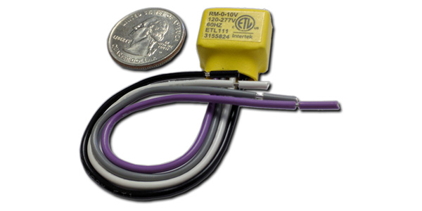
Connected to the fixture power and to the LED Driver is a small low-cost receiving module that monitors the power line for these messages and translates them into the 0-10V input of the fixture. The receiving module is very resilient in detecting these power line markers as it uses the patented method of evaluating the power line. Even in situations where the power line noise is present, it will not miss the start and stop marks nor will it interpret missing power line cycles caused by external factors that fall outside the marks it is looking for.
The biggest advantage is there is no need to run low voltage 0-10V wires from the dimmer to the fixtures. Normally contractors would have to visit every jobsite to understand what running low voltage wiring would cost. Using Relay Dimming products the contractor only has to change the fixtures and the dimmer and he is finished. He can know the cost of the job before visiting the site. Now a two-man job can be a one-man job.
One other important advantage of this method is that it is not in any way the older style of communication over the power line. It isn’t Power Line Carrier, Pulse Position Modulation, Spread Spectrum, or any of the similar methods. It is impossible for this signal method to go backwards into the circuits of the building and is impossible for anything in the building to attenuate the missing ½ cycles. The relay load line goes only to the fixtures on the load line. PCS has an ongoing project to test reliability over time, and no situations have been found where powerline noise or other anomalies have caused this system to fail.
By using Relay Dimming, you can provide extra value to your customers at no extra cost to you – that helps you win bids – plus without all those unknowns that come with running wires you can bid a retrofit job with confidence.
PCS has developed the Relay Dimming products in two versions. One version is part of its PulseWorx product line where it can be incorporated into a PulseWorx Automation Network. The second version is a “stand-alone” non-PulseWorx product line intended for general contractor use where a control switch or keypad controls one or more LED fixtures.
The PulseWorx and this new contractor Relay Dimming lines are available now. For more information visit: www.pcslighting.com.